
|
|
|

|
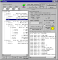
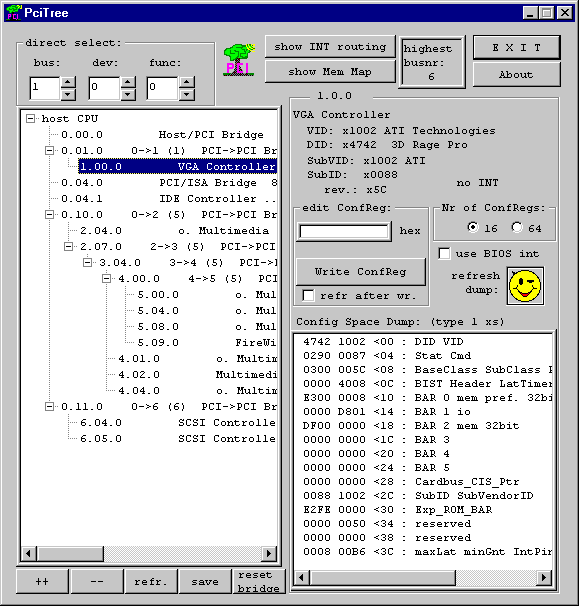
The main window of PCItree shows the structure of the PCIbus on the left side. The config registers of the selected device (here: VGA controller) are displayed on the right lower side. On top of this Config space dump information of some registers is dsiplayed in more detail.
There is also a field for editing a dword of a config register. To do so select a config register change the value and click write to write that value back into the register.
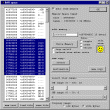
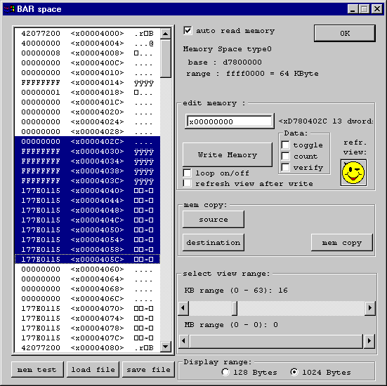
The memory window of PCItree is opened when a BAR of the config register in the main window is double clicked.
The memory window shows on the left side a memory range of 1 kByte. The range can be changed by the two sliders on the right lower side.
You can change one dword of the memory by selecting one address in left view. The value of that memory location can be changed in the edit box on the right side.
The write function has more options if a address range is selected instead of a single address.
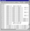
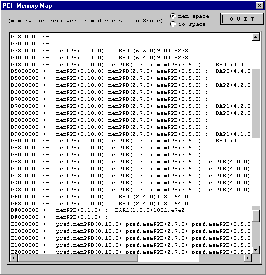
The memory map of the PCIbus is displayed with a granularity of 8 MByte. Shown are the PCI to PCI bridges and the BARs which are mapped to this address range.
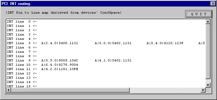
The first 16 Interrupt lines of the host controller are listed. The config registers of all devices are searched for which INT pin is routed to which line of the controller. The devices are listed with their INT pin (A to D), their b.d.f (bus.device.function number)and their VID and DID.
